Hard-wired Serial Terminal Handset
Overview
This is a prototype device that I built to primarily communicate with Traffic Signal Controllers using the RS232 serial protocol. Using this device I can interrogate faults, update settings and monitor the status of a connected controller.
Although not as pretty, my handset can be used in exactly the same way as many ‘off-the-shelf’ devices, but I have added some additional functionality which I deemed helpful in common maintenance situations.
Project completion date – April 2025
A showcase video can be found at the bottom of this page.
Hardware
One of the main reasons I decided to build this prototype was simply because I had recently discovered what a ‘button matrix’ was and how it worked. I found it absolutely fascinating how, through the use of a button array and some precisely placed diodes, the microcontroller could decipher and single out one individual button press and take action.
Most of my work leading up to this project had revolved around serial communication devices and the RS232 protocol, so the idea of incorporating my prior knowledge with my interest in this new concept came naturally. The thought of having my very own custom device gave me the freedom to brainstorm all the ways I’d improve the generic handset device issued to me at work and, as you’ll read below, I managed to implement quite a few of them.
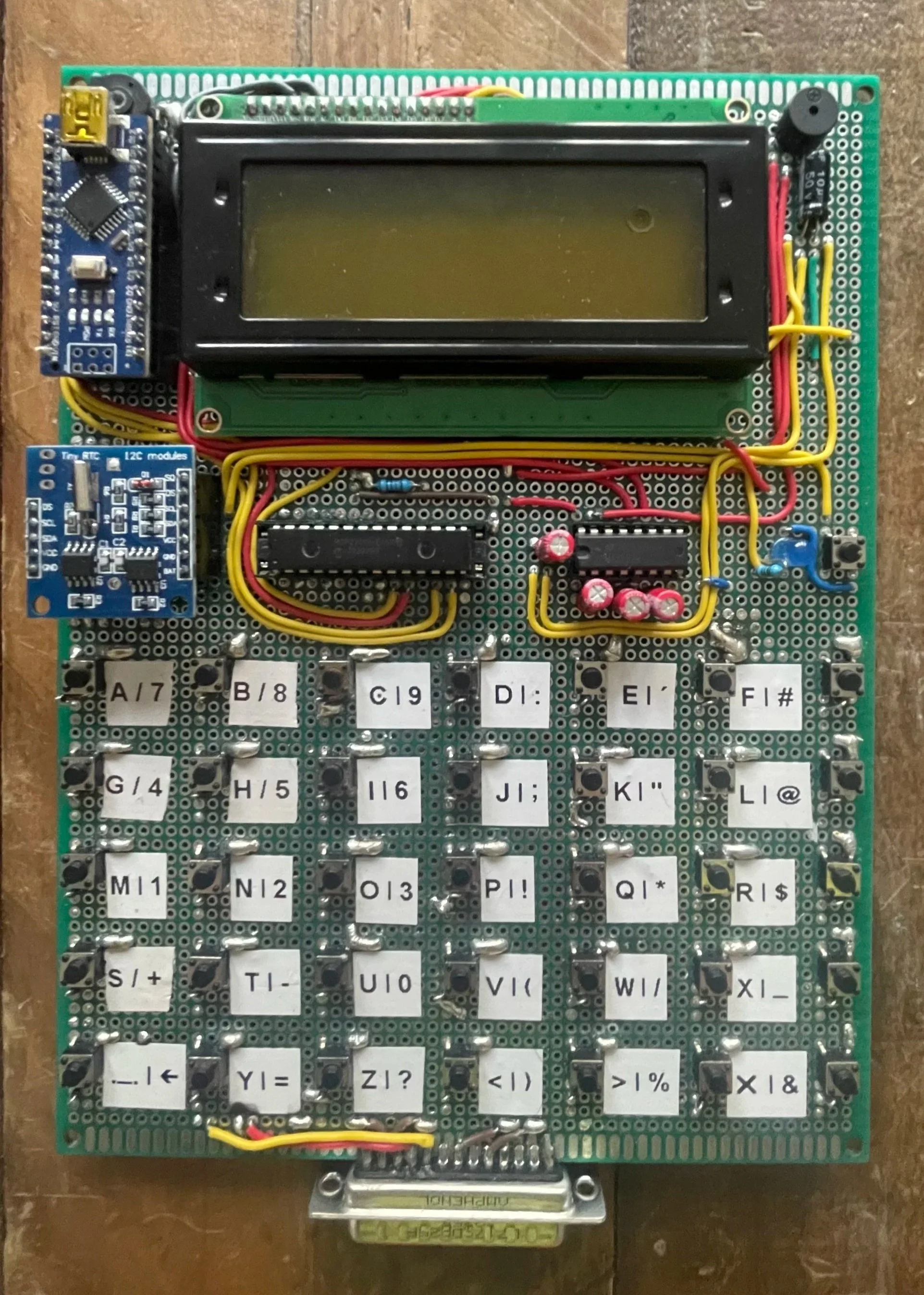
The brain of this device is an Arduino Nano microcontroller, which can be seen in the top left corner of the board. The Nano handles every operation, from receiving and transmitting serial data to displaying that data to the user via the large LCD screen. It also reads the user’s inputs from the character keys and takes the appropriate action. Communication with an RTC module, located below the Arduino on the left, is also handled by the Nano via the I2C protocol to keep track of the time and date.
Other than the Arduino and the RTC module, there are two other chips on this board. Moving to the right of the RTC module, we first have a 16-bit input/output expander chip, and then a MAX232N TTL–RS232 interface chip.
The main reason I chose to use an Arduino Nano microcontroller was its compact size, allowing all components to fit on a single board. However, this introduced the issue of not having enough I/O pins to accommodate all my planned modules. With the button matrix alone using 12 pins, I was going to run into a problem. Fortunately, I came across the I/O expander chip, which gave me access to an additional 16 pins — more than enough. This IC and the RTC module communicate with the Arduino via an I2C serial bus, which was something I hadn’t used before and required me to do some research.
Another drawback of the Arduino Nano, in this specific use case, is that it uses TTL voltage levels when communicating via serial, which aren’t compatible with the RS232 levels that Traffic Signal Controllers use. Thankfully, this was a problem I had encountered and overcome in previous projects, so it was simply a case of placing the MAX232N chip and the required capacitors on the board and soldering the connections to resolve the voltage mismatch.
The remaining hardware is simpler in comparison. In the top right is a small piezo buzzer. This plays a short tone after each button press to provide audible feedback that the input was received, and it also plays a longer start-up tune when the device is first powered on. The buzzer can be muted within the multi-page menu if desired, and the start-up sequence can be shortened for more efficient use.
Below the buzzer and to the right of the MAX232N chip is a small blue LED and micro-switch. This switch is not part of the matrix. Its only function is to connect the LED’s positive pin to the coin cell battery built into the RTC module. When pressed, it completes the circuit and illuminates the LED if the battery still has charge. This allows the user to monitor the RTC module and ensure it remains powered and keeping time even when the main device is switched off.
Lastly, at the very bottom of the board, there is a 25-way male D-sub connector. This can be used with a ribbon cable extender to plug the device directly into a Traffic Signal Controller engineer’s port and begin communication.
Software
Creating the software for this device was by far the more difficult portion of the project and probably my greatest challenge to date. So much time and effort went into the part that handles incoming and outgoing serial data, which by the end of the project actually turned out to be one of the simpler functions.
The first thing users are met with when powering on the device is a start-up sequence. A dashed line makes its way around the edge of the screen whilst a tone plays at each interval, concluding by displaying ‘BEP-TECH’ in the centre. It runs for about four seconds in total, but I added the option to shorten this to half a second within the main menu (Having to wait every time I restarted the device during testing led me to add this feature). Once either version of the start-up sequence has run, the device goes straight into operation. The cursor flashes eagerly on the screen whilst it waits to receive incoming data or user inputs from the keys. I have assigned ASCII characters to all of the keys (as can be seen by the corresponding label to the right of each key), apart from the last column on the right, as these are reserved for special functions.
Starting at the top, we have the SHIFT key. This allows users to select one of two different characters per key, effectively doubling the number of available characters. Next, we have the PRESETS key. This adds another layer of functionality by allowing users to send a previously saved value of up to six characters with a single key press, meaning entire commands can be sent with one click. Along with the SHIFT key, the PRESETS key must be held whilst another key is pressed to send the desired value. In the middle of the row is the MENU key, which allows users to open the menu system and change serial settings, save or edit preset commands, update or check the time and date, and adjust certain functions based on personal preference. Just below the MENU key is the TOD/CAL key. Once pressed, this key transmits the real time at the moment of button press in the correct format to set the time of the Traffic Signal Controller — for example: TOD=12:30:00. Pressing this button whilst holding the SHIFT key does the same for the date — for example: CAL=01:01:2026. Lastly, we have the ENT key. Inside the menus, this acts as a select button, but outside of them it functions as a transmittable ASCII character.
The menu consists of four pages with up to four settings or options on each. The currently selected setting is highlighted with a pair of angled brackets on either side of the screen. Users can press the PRESETS key (UP) or the TOD/CAL key (DOWN) to navigate through the menu. Settings with a limited number of values can be changed directly from this screen by pressing the ENT key. This cycles the selected value to the next option in the list before looping back round to the start. The editable settings and options are as follows:
BAUDRATE – 300, 600, 1200, 2400, 9600
DATA-BITS – 7, 8
PARITY – EVEN, ODD, IGNORE
DISPLAY-PE – ON, OFF
REPEAT – OFF, SLOW, FAST
ECHO – ON, OFF
HANDSHAKE – ON, OFF
STARTUP – ON, OFF
SPEAKER – ON, OFF
CLOCK
PRESETS
BRIGHTNESS
WIPE-MEMORY
Baud rate, data bits and parity are characteristics of RS232 serial communication. This protocol does not use a clock signal to synchronise transmission like other protocols, so both communicating devices must be set to the same configuration to ensure all received data is interpreted correctly. By default, this device is set to 1200, 7, EVEN, as that is what most Traffic Signal Controllers use. However, I wanted to build something flexible that could be used with a wide range of systems, hence the multiple options. Display-PE refers to the ‘Parity Error’ symbol. Terminals, including mine, display this when a received byte fails the parity check (comparing received data against the expected parity setting), signalling either a communication mismatch or corrupted data. Repeat allows the user to decide what happens when a key is held down. OFF sends the character once and waits until the key is released. SLOW and FAST continue sending the character whilst the key remains pressed, just at different speeds. When a character is transmitted from the terminal, it is not printed to the screen — only received data is displayed. In normal operation, the receiving controller returns the incoming character, meaning the terminal receives and therefore prints the character it has just transmitted. However, if no device is connected, nothing will be displayed when keys are pressed. Echo changes this behaviour by printing the character locally as well as transmitting it. This allows users to see what they are typing even when no device is connected. However, if a device is connected, characters will appear twice each time a key is pressed. Handshake is used to control the flow of data between two devices. It allows both devices to determine when it is safe to send data and enables transmission to pause if either device’s serial buffer is full. Once the backlog is cleared, data flow resumes. I have already briefly touched on Start-up and Speaker. These settings allow users to personalise how long the start-up sequence runs and whether the buzzer emits a tone after each key press.
The last four settings in the menu — Clock, Presets, Brightness and Wipe-memory — are more involved than the others and therefore have their own sub-menus. The user can press the ENT key to enter a sub-menu and, once inside, press the MENU key to return to the main menu. Pressing MENU whilst in the main menu exits back to the standard terminal screen, saving all settings to EEPROM in the process.
Clock
Within the Clock sub-menu, there are three self-explanatory options: View-time, Set-time and Set-date.
Pressing ENT on any of these allows interaction with that function. View-time simply displays the current time and date stored in the RTC module and updates every second. The device continues displaying this until any key is pressed, at which point the user is returned to the Clock sub-menu.
Set-time and Set-date operate in similar ways and allow the user to quickly change the stored values. This was far more involved than I initially thought. After each character entry, the device checks that the input is numeric and then verifies that it is valid for that specific unit of time or date. For example, it will not allow values above ‘23’ in the hours field or above ‘59’ in the minutes and seconds fields. The date function also prevents mismatches between days and months, making it impossible to enter something like the 31st of February.
Presets
Once inside the Presets menu, the user is prompted to press any key to begin. If a special function key from the far-right column is selected, a short message informs the user that these keys cannot be used.
After selecting a valid key, its reference number is displayed at the top of the screen. A is 01, B is 02, and so on up to 34.
If no preset is currently saved to that key, the user is prompted to enter one. Each preset can contain between one and six characters, including letters, numbers and special characters (for example, ‘MAX=15’). If the preset is shorter than six characters, pressing ENT saves only the entered characters.
If a preset already exists, it is displayed under the heading ‘CURRENT PRESET’. Users can use this to remind themselves of existing assignments. If they wish to change it, pressing ENT gives them the option to clear the saved data. Pressing MENU cancels the reset, while pressing ENT again confirms it. Once cleared, the user is returned to the preset entry screen.
Brightness
Unfortunately, when the user selects this option they are greeted with a screen displaying ‘Coming soon’.
The brightness — or more accurately, contrast — of the LCD screen is controlled by the voltage supplied to the V0 pin. This can be adjusted using a potentiometer to alter the resistance between VCC and V0. There is a physical potentiometer fitted above the Arduino board, but I wanted this to be software-adjustable.
After researching, the only practical solution would be to use a digital potentiometer chip between VCC and V0 and control it via the Arduino. This required more redesign work than I had initially planned, so I decided to leave it for the time being and prioritise other functionality.
I originally pursued this feature because I noticed the screen contrast varied slightly depending on whether the device was powered by a laptop, power bank or Traffic Signal Controller. As laptop power was primarily for testing, I optimised the contrast for use with controllers instead.
Any key can be pressed to exit this screen.
Wipe-memory
This is the final option in the menu, and it does exactly what it says on the tin. All user-created data — from serial settings and preferences to presets — is saved in the Arduino’s EEPROM. This means the data remains stored even when the device is unplugged. Unlike ordinary variables, which reset on power-up, the device reads its stored EEPROM values each time it powers on and automatically applies the previously saved settings. Pressing ENT asks the user to confirm the action. Pressing MENU cancels it, and pressing ENT again wipes all saved data and restores default values.
So many things went wrong during this project that I genuinely began to question whether I would ever finish it. Getting the button matrix to return the correct key press was something I really struggled with at the start. This was my first real project using an I2C bus to allow the Arduino to communicate with other modules, and it was the physical connections that caused most of the confusion.
I initially had issues with the voltage levels on the SDA and SCL lines, resulting in data not being transferred correctly. I later realised the lines needed pull-up resistors to VCC, with the devices themselves pulling the lines low when transmitting data. I was certain this would fix everything — but it still wasn’t working. After exhausting what I could find online, I went back through my own work and eventually discovered a poorly soldered connection. I corrected it and, to my relief, everything began working as expected.
Once the button matrix was functioning reliably, I gained the momentum to push forward with the main handset features. I later encountered further issues when attempting to implement some of the more advanced serial settings. I tried to replicate all of the basic features of the terminal handset I use day to day at work — the idea being that my device would match it in capability, and then add extra functionality on top. The off-the-shelf handset allows users to select ‘MARK’ and ‘SPACE’ as parity options, which force the parity bit permanently to 1 or 0. There was no real requirement for me to include this, as it does not contribute to parity error checking, but I wanted to replicate as much functionality as possible. The issue was that the Arduino does not support forcing the parity bit in this way. Only certain serial configurations are available. I attempted to work around this by modifying the Arduino source code, but ultimately it would have required a different microcontroller. As it was not an essential feature, I decided I was wasting time pursuing it and accepted the functionality I already had.
This project taught me a huge amount about serial communication and various protocols. It reinforced my existing Arduino knowledge and pushed me to explore the limits of what I could implement. I also improved my coding structure, reducing repetition and leaving detailed notes for my future self, which helped significantly.
Overall, I am incredibly happy with the outcome of this project and proud of myself for seeing it through. What started as a small idea is now something I can physically hold and even use at work to make life a little easier. Facing numerous technical challenges — both electronic and programming related — was tough, but I managed to overcome most of them and made peace with the ones I couldn’t. I definitely pushed myself with this project and feel like a much stronger engineer because of it.
It is not a perfect device, and I have realised it never will be. There will always be improvements to make. However, I reached a point where I was genuinely happy with it, which allowed me to move on to new projects. I would like to revisit it one day, starting with implementing a proper software-controlled contrast setting using a digital potentiometer. I would also love to design a protective enclosure so it can be used outdoors in various weather conditions without concern. That will be challenging however, as the original design did not account for it, but it is something I would enjoy tackling.
Please see the video below showcasing all of the features mentioned above. Thank you!